nRF24L01 + DualShock2 = радиоуправление
Я, наконец-то решился купить модули nRF24L01. Для знакомства с ними нужно придумать что из них сделать. И сделал радиоуправляемую машинку. Из всего, что есть.
Наверное, все в детстве хотели радиоуправляемую машинку :)
Выглядят модули вот так:
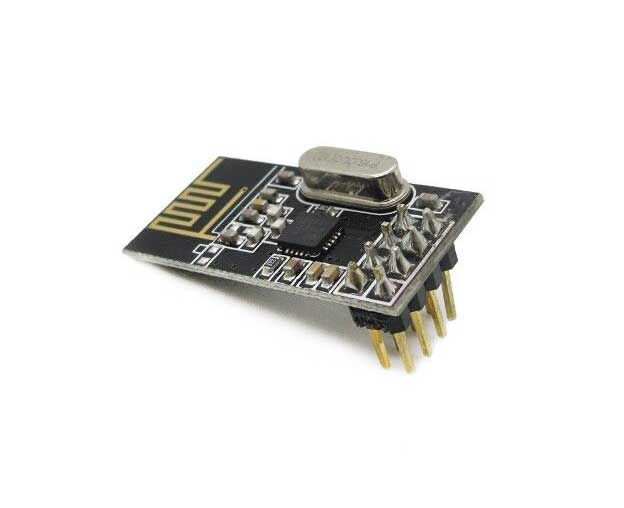
Описание:
Дальность до 100 м. Скорость до 2 Мб Интерфейс SPI для управления Напряжение: 3-3.6В (рекомендуется 3,3) В Максимальная выходная мощность: +20 дБм Коэффициент усиления антенны (пиковая): 2dBi
Работает радиомодуль на частоте 2.4ГГц (как эти ваши вайфаи и блютузы).
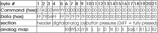
В качестве пульта я решил использовать тот самый белый геймпад (он не обиделся). Нормальных библиотек особо не нашёл, почитал мануал, посмотрел структуру пакета (рисунок 2), решил написать сам. Геймпад общается по протоколу SPI.
Вроде бы ничего сложного, написал. Подключил экран и проверил. Работает:
И всё работало замечательно пока не отключили свет. И так повезло, что после этого все исходники превратились в кровавое месиво. И тут я случайно нашёл другую библиотеку и взял ее.
После обработки напильником библиотека стала иметь более-менее приличный вид:
psx.h:
#ifndef PSX_lib_h
#define PSX_lib_h

#include <avr/io.h>
#include <stdbool.h>


#define PSX_DATA_PORT   PORTD
#define PSX_SCK_PORT    PORTD
#define PSX_DC_PORT     PORTD
#define PSX_CS_PORT     PORTD

#define PSX_DATA_PINREG PIND

#define PSX_DATA_DDR    DDRD
#define PSX_SCK_DDR     DDRD
#define PSX_DC_DDR      DDRD
#define PSX_CS_DDR      DDRD

#define  PSX_SCK_PIN    4
#define  PSX_DC_PIN     7
#define  PSX_CS_PIN     5
#define  PSX_DATA_PIN   6

// задержка тактов SPI, us
#define CTRL_CLK        10

// кнопкм
#define PSB_SELECT      0x0001
#define PSB_L3          0x0002
#define PSB_R3          0x0004
#define PSB_START       0x0008
#define PSB_PAD_UP      0x0010
#define PSB_PAD_RIGHT   0x0020
#define PSB_PAD_DOWN    0x0040
#define PSB_PAD_LEFT    0x0080
#define PSB_L2          0x0100
#define PSB_R2          0x0200
#define PSB_L1          0x0400
#define PSB_R1          0x0800
#define PSB_TRIANGLE    0x1000
#define PSB_CIRCLE      0x2000
#define PSB_CROSS       0x4000
#define PSB_SQUARE      0x8000

// джойстики
#define PSS_RX 5
#define PSS_RY 6
#define PSS_LX 7
#define PSS_LY 8


// инициализация геймпада
void psx_init(bool analog);

// получить состояние всех кнопок
uint16_t psx_buttons();

// получить состояниие кнопки (PSB_x)
uint8_t psx_button(uint16_t);

// получить состояниие оси джойстика (PSS_x)
uint8_t psx_stick(unsigned int);

// обновить состояние кнопок
void psx_read_gamepad();

#endif
psx.c:
#include "psx.h"
#include <util/delay.h>

// буфер
static uint8_t _psx_data[21];

// отправить байт программным SPI и получить ответ
uint8_t _psx_gamepad_shift(uint8_t transmit_byte) {
    uint8_t received_byte = 0;
    for(uint8_t i = 0; i < 8; i++) {
        PSX_SCK_PORT &= ~_BV(PSX_SCK_PIN);

        if (transmit_byte & (_BV(i))) {
            PSX_DC_PORT |= _BV(PSX_DC_PIN);
        }
        else {
            PSX_DC_PORT &= ~_BV(PSX_DC_PIN);
        }

        _delay_us(CTRL_CLK);

        PSX_SCK_PORT |= _BV(PSX_SCK_PIN);

        if(PSX_DATA_PINREG & _BV(PSX_DATA_PIN)) {
            received_byte |= _BV(i);
        }

        _delay_us(CTRL_CLK);
    }

    PSX_SCK_PORT |= _BV(PSX_SCK_PIN);

    return received_byte;
}

// отправить команду
void _psx_send_command(uint8_t send_data[], uint8_t size){
    PSX_CS_PORT &= ~(_BV(PSX_CS_PIN));
    PSX_DC_PORT |= _BV(PSX_DC_PIN);

    PSX_SCK_PORT |= _BV(PSX_SCK_PIN);

    for (uint8_t i = 0; i < size; i++){
        send_data[i] = _psx_gamepad_shift(send_data[i]);
    }

    PSX_CS_PORT |= _BV(PSX_CS_PIN);
}

// обновить состояние кнопок
void psx_read_gamepad() {
    _psx_data[0] = 0x01;
    _psx_data[1] = 0x42;
    for (uint8_t i = 2; i < 21; i++){
        _psx_data[i] = 0x00;
    }
    _psx_send_command(_psx_data, 21);
}

// инициализация геймпада
void psx_init(bool analog){

    PSX_SCK_DDR |= _BV(PSX_SCK_PIN);
    PSX_CS_DDR |= _BV(PSX_CS_PIN);
    PSX_DC_DDR |= _BV(PSX_DC_PIN);

    PSX_DATA_DDR &= ~(_BV(PSX_DATA_PIN));
    PSX_DATA_PORT |= _BV(PSX_DATA_PIN);

    PSX_SCK_PORT |= _BV(PSX_SCK_PIN);
    PSX_DC_PORT |= _BV(PSX_DC_PIN);

    psx_read_gamepad();

    if(!analog) return;

    // войти в режим конфигурации
    uint8_t enter_config_command[] = {0x01, 0x43, 0x00, 0x01, 0x00};
    _psx_send_command(enter_config_command, 5);

    // заблокирвать геймпад в аналоговом режиме
    uint8_t lock_analog_mode_command[] = {0x01, 0x44, 0x00, 0x01, 0x03, 0x00, 0x00, 0x00, 0x00};
    _psx_send_command(lock_analog_mode_command, 9);

    // выйти из режима конфигурации
    uint8_t exit_config_command[] = {0x01, 0x43, 0x00, 0x00, 0x5A, 0x5A, 0x5A, 0x5A, 0x5A};
    _psx_send_command(exit_config_command, 9);
}

// получить состояние всех кнопок
uint16_t psx_buttons() {
    uint16_t buttons = *(uint16_t*)(_psx_data + 3); // получить 2 байта, содержащих позиции данных 3 и 4
    return ~buttons;
}

// получить состояниие кнопки (PSB_x
uint8_t psx_button(uint16_t button) {
    uint16_t buttons = psx_buttons();
    return ((buttons & button) > 0);
}

// получить состояниие оси джойстика (PSS_x)
uint8_t psx_stick(unsigned int stick) {
    return _psx_data[stick];
}
Код передатчика:
host.c:
#define NRF24_IO_PORT PORTC
#define NRF24_IO_PINREG PINC
#define NRF24_IO_DDR DDRC

#include <avr/io.h>
#include <util/delay.h>
#include "lib/nrf24.h"
#include "lib/psx.h"

//      ATMega8        nrf24
//     ________      _________
//    |    PC0 |----| CE      |
//    |    PC1 |----| CSN     |
//    |    PC2 |----| SCK     |
//    |    PC3 |----| MOSI    |
//    |    PC4 |----| MISO    |
//    |        |    |_________|
//    |        |
//    |        |      Геймпад
//    |        |     _________
//    |    PD4 |----| SCK     |
//    |    PD5 |----| CS      |
//    |    PD6 |----| DATA    |
//    |    PD7 |----| DC      |
//    |________|    |_________|


uint8_t data_array[2];
uint8_t tx_address[5] = {0xE7, 0xE7, 0xE7, 0xE7, 0xE7};
uint8_t rx_address[5] = {0xD7, 0xD7, 0xD7, 0xD7, 0xD7};


int main() {

    nrf24_init();

    nrf24_config(2, 2); // канал 2, размер пакета 2

    nrf24_tx_address(tx_address);
    nrf24_rx_address(rx_address);

    psx_init(false);

    while (1) {

        psx_read_gamepad(); // чтение геймпада

        data_array[0] = 0xFE; // проверочное значение

        // вверх       - левое  шасси вперёд
        // вниз        - левое  шасси назад
        // треугольник - правое шасси вперёд
        // крест       - правое шасси назад
        data_array[1] = (psx_button(PSB_PAD_UP) << 1) | (psx_button(PSB_PAD_DOWN) << 2)
                        | (psx_button(PSB_TRIANGLE) << 3) | (psx_button(PSB_CROSS) << 4); // запихиваем кнопки

        nrf24_send(data_array); // отправляем данные
        while (!nrf24_isSending());

        _delay_ms(20);

    }
}
Код черепахи:
turtle.c:
#include <avr/io.h>
#include "lib/nrf24.h"
#include <util/delay.h>
#include <stdbool.h>

//      ATMega8        nrf24
//     ________      _________
//    |    PC0 |----| CE      |
//    |    PC1 |----| CSN     |
//    |    PC2 |----| SCK     |
//    |    PC3 |----| MOSI    |
//    |    PC4 |----| MISO    |
//    |        |    |_________|
//    |        |
//    |        |             Шасси
//    |    PD0 |-(2)  (1)--[/\   /\]--(3)
//    |    PD1 |-(1)       |L|   |R|
//    |    PD2 |-(3)       |L|   |R|
//    |    PD3 |-(4)  (2)--[\/   \/]--(4)
//    |________|

uint8_t data_array[2];
uint8_t tx_address[5] = {0xD7, 0xD7, 0xD7, 0xD7, 0xD7};
uint8_t rx_address[5] = {0xE7, 0xE7, 0xE7, 0xE7, 0xE7};

#define ENGINES_PORT            PORTD
#define ENGINES_DDR             DDRD

#define LEFT_CHASSIS_FWD_PIN    1
#define LEFT_CHASSIS_REV_PIN    0

#define RIGHT_CHASSIS_FWD_PIN   3
#define RIGHT_CHASSIS_REV_PIN   2

int main() {

    ENGINES_DDR |= 0b00001111;
    nrf24_init();

    nrf24_config(2, 2); // канал 2, размер пакета 2

    nrf24_tx_address(tx_address);
    nrf24_rx_address(rx_address);


    while (1) {

        if (nrf24_dataReady()) nrf24_getData(data_array);

        if (data_array[0] == 0xFE) { // проверка типа пакета
            bool left_fw = (data_array[1] & (1 << 1)) != 0;
            bool left_bck = (data_array[1] & (1 << 2)) != 0;
            bool right_fw = (data_array[1] & (1 << 3)) != 0;
            bool right_bck = (data_array[1] & (1 << 4)) != 0;
            ENGINES_PORT = (left_fw << LEFT_CHASSIS_FWD_PIN) | (right_fw << RIGHT_CHASSIS_FWD_PIN) |
                           (left_bck << LEFT_CHASSIS_REV_PIN) | (right_bck << RIGHT_CHASSIS_REV_PIN);
        }

        _delay_ms(20);

    }
}
/* ------------------------------------------------------------------------- */
Библиоткека для nRF24:
nrf24.h:
/*
* ----------------------------------------------------------------------------
* “THE COFFEEWARE LICENSE” (Revision 1):
* <[email protected]> wrote this file. As long as you retain this notice you
* can do whatever you want with this stuff. If we meet some day, and you think
* this stuff is worth it, you can buy me a coffee in return.
* -----------------------------------------------------------------------------
* This library is based on this library:
*   https://github.com/aaronds/arduino-nrf24l01
* Which is based on this library:
*   http://www.tinkerer.eu/AVRLib/nRF24L01
* -----------------------------------------------------------------------------
*/
#ifndef NRF24
#define NRF24

#include <stdint.h>
#include <avr/io.h>

#ifdef TURTLE
#define NRF24_IO_PORT   PORTB
#define NRF24_IO_PINREG PINB
#define NRF24_IO_DDR    DDRB
#else
#define NRF24_IO_PORT   PORTC
#define NRF24_IO_PINREG PINC
#define NRF24_IO_DDR    DDRC
#endif


#define NRF24_CE_PIN   0
#define NRF24_CSN_PIN  1
#define NRF24_SCK_PIN  2
#define NRF24_MOSI_PIN 3
#define NRF24_MISO_PIN 4


/* IO Helpers */
#define nrf24_set_bit(reg,bit) reg |= (1<<bit)
#define nrf24_clr_bit(reg,bit) reg &= ~(1<<bit)
#define nrf24_check_bit(reg,bit) (reg&(1<<bit))

/* Memory Map */
#define CONFIG      0x00
#define EN_AA       0x01
#define EN_RXADDR   0x02
#define SETUP_AW    0x03
#define SETUP_RETR  0x04
#define RF_CH       0x05
#define RF_SETUP    0x06
#define STATUS      0x07
#define OBSERVE_TX  0x08
#define CD          0x09
#define RX_ADDR_P0  0x0A
#define RX_ADDR_P1  0x0B
#define RX_ADDR_P2  0x0C
#define RX_ADDR_P3  0x0D
#define RX_ADDR_P4  0x0E
#define RX_ADDR_P5  0x0F
#define TX_ADDR     0x10
#define RX_PW_P0    0x11
#define RX_PW_P1    0x12
#define RX_PW_P2    0x13
#define RX_PW_P3    0x14
#define RX_PW_P4    0x15
#define RX_PW_P5    0x16
#define FIFO_STATUS 0x17
#define DYNPD       0x1C

/* Bit Mnemonics */

/* configuratio nregister */
#define MASK_RX_DR  6
#define MASK_TX_DS  5
#define MASK_MAX_RT 4
#define EN_CRC      3
#define CRCO        2
#define PWR_UP      1
#define PRIM_RX     0

/* enable auto acknowledgment */
#define ENAA_P5     5
#define ENAA_P4     4
#define ENAA_P3     3
#define ENAA_P2     2
#define ENAA_P1     1
#define ENAA_P0     0

/* enable rx addresses */
#define ERX_P5      5
#define ERX_P4      4
#define ERX_P3      3
#define ERX_P2      2
#define ERX_P1      1
#define ERX_P0      0

/* setup of address width */
#define AW          0 /* 2 bits */

/* setup of auto re-transmission */
#define ARD         4 /* 4 bits */
#define ARC         0 /* 4 bits */

/* RF setup register */
#define PLL_LOCK    4
#define RF_DR       3
#define RF_PWR      1 /* 2 bits */

/* general status register */
#define RX_DR       6
#define TX_DS       5
#define MAX_RT      4
#define RX_P_NO     1 /* 3 bits */
#define TX_FULL     0

/* transmit observe register */
#define PLOS_CNT    4 /* 4 bits */
#define ARC_CNT     0 /* 4 bits */

/* fifo status */
#define TX_REUSE    6
#define FIFO_FULL   5
#define TX_EMPTY    4
#define RX_FULL     1
#define RX_EMPTY    0

/* dynamic length */
#define DPL_P0      0
#define DPL_P1      1
#define DPL_P2      2
#define DPL_P3      3
#define DPL_P4      4
#define DPL_P5      5

/* Instruction Mnemonics */
#define R_REGISTER    0x00 /* last 4 bits will indicate reg. address */
#define W_REGISTER    0x20 /* last 4 bits will indicate reg. address */
#define REGISTER_MASK 0x1F
#define R_RX_PAYLOAD  0x61
#define W_TX_PAYLOAD  0xA0
#define FLUSH_TX      0xE1
#define FLUSH_RX      0xE2
#define REUSE_TX_PL   0xE3
#define ACTIVATE      0x50
#define R_RX_PL_WID   0x60
#define NOP           0xFF

#define LOW 0
#define HIGH 1

#define nrf24_ADDR_LEN 5
#define nrf24_CONFIG ((1<<EN_CRC)|(0<<CRCO))

#define NRF24_TRANSMISSON_OK 0
#define NRF24_MESSAGE_LOST   1

/* IO functions */
void nrf24_setupPins();
void nrf24_ce_digitalWrite(uint8_t state);
void nrf24_csn_digitalWrite(uint8_t state);
void nrf24_sck_digitalWrite(uint8_t state);
void nrf24_mosi_digitalWrite(uint8_t state);
uint8_t nrf24_miso_digitalRead();

/* adjustment functions */
void    nrf24_init();
void    nrf24_rx_address(uint8_t* adr);
void    nrf24_tx_address(uint8_t* adr);
void    nrf24_config(uint8_t channel, uint8_t pay_length);

/* state check functions */
uint8_t nrf24_dataReady();
uint8_t nrf24_isSending();
uint8_t nrf24_getStatus();
uint8_t nrf24_rxFifoEmpty();

/* core TX / RX functions */
void    nrf24_send(uint8_t* value);
void    nrf24_getData(uint8_t* data);

/* use in dynamic length mode */
uint8_t nrf24_payloadLength();

/* post transmission analysis */
uint8_t nrf24_lastMessageStatus();
uint8_t nrf24_retransmissionCount();

/* Returns the payload length */
uint8_t nrf24_payload_length();

/* power management */
void    nrf24_powerUpRx();
void    nrf24_powerUpTx();
void    nrf24_powerDown();

/* low level interface ... */
uint8_t spi_transfer(uint8_t tx);
void    nrf24_transmitSync(uint8_t* dataout,uint8_t len);
void    nrf24_transferSync(uint8_t* dataout,uint8_t* datain,uint8_t len);
void    nrf24_configRegister(uint8_t reg, uint8_t value);
void    nrf24_readRegister(uint8_t reg, uint8_t* value, uint8_t len);
void    nrf24_writeRegister(uint8_t reg, uint8_t* value, uint8_t len);

/* -------------------------------------------------------------------------- */
/* You should implement the platform spesific functions in your code */
/* -------------------------------------------------------------------------- */

/* -------------------------------------------------------------------------- */
/* In this function you should do the following things:
 *    - Set MISO pin input
 *    - Set MOSI pin output
 *    - Set SCK pin output
 *    - Set CSN pin output
 *    - Set CE pin output     */
/* -------------------------------------------------------------------------- */
extern void nrf24_setupPins();

/* -------------------------------------------------------------------------- */
/* nrf24 CE pin control function
 *    - state:1 => Pin HIGH
 *    - state:0 => Pin LOW     */
/* -------------------------------------------------------------------------- */
extern void nrf24_ce_digitalWrite(uint8_t state);

/* -------------------------------------------------------------------------- */
/* nrf24 CE pin control function
 *    - state:1 => Pin HIGH
 *    - state:0 => Pin LOW     */
/* -------------------------------------------------------------------------- */
extern void nrf24_csn_digitalWrite(uint8_t state);

/* -------------------------------------------------------------------------- */
/* nrf24 SCK pin control function
 *    - state:1 => Pin HIGH
 *    - state:0 => Pin LOW     */
/* -------------------------------------------------------------------------- */
extern void nrf24_sck_digitalWrite(uint8_t state);

/* -------------------------------------------------------------------------- */
/* nrf24 MOSI pin control function
 *    - state:1 => Pin HIGH
 *    - state:0 => Pin LOW     */
/* -------------------------------------------------------------------------- */
extern void nrf24_mosi_digitalWrite(uint8_t state);

/* -------------------------------------------------------------------------- */
/* nrf24 MISO pin read function
/* - returns: Non-zero if the pin is high */
/* -------------------------------------------------------------------------- */
extern uint8_t nrf24_miso_digitalRead();

#endif
nrf24.c:
/*
* ----------------------------------------------------------------------------
* “THE COFFEEWARE LICENSE” (Revision 1):
* <[email protected]> wrote this file. As long as you retain this notice you
* can do whatever you want with this stuff. If we meet some day, and you think
* this stuff is worth it, you can buy me a coffee in return.
* -----------------------------------------------------------------------------
* This library is based on this library:
*   https://github.com/aaronds/arduino-nrf24l01
* Which is based on this library:
*   http://www.tinkerer.eu/AVRLib/nRF24L01
* -----------------------------------------------------------------------------
*/
#include "nrf24.h"

uint8_t payload_len;

void nrf24_setupPins() {
    nrf24_set_bit(NRF24_IO_DDR, NRF24_CE_PIN); // CE output
    nrf24_set_bit(NRF24_IO_DDR, NRF24_CSN_PIN); // CSN output
    nrf24_set_bit(NRF24_IO_DDR, NRF24_SCK_PIN); // SCK output
    nrf24_set_bit(NRF24_IO_DDR, NRF24_MOSI_PIN); // MOSI output
    nrf24_clr_bit(NRF24_IO_DDR, NRF24_MISO_PIN); // MISO input
}

void nrf24_ce_digitalWrite(uint8_t state) {
    if (state) {
        nrf24_set_bit(NRF24_IO_PORT, NRF24_CE_PIN);
    }
    else {
        nrf24_clr_bit(NRF24_IO_PORT, NRF24_CE_PIN);
    }
}

void nrf24_csn_digitalWrite(uint8_t state) {
    if (state) {
        nrf24_set_bit(NRF24_IO_PORT, NRF24_CSN_PIN);
    }
    else {
        nrf24_clr_bit(NRF24_IO_PORT, NRF24_CSN_PIN);
    }
}


void nrf24_sck_digitalWrite(uint8_t state) {
    if (state) {
        nrf24_set_bit(NRF24_IO_PORT, NRF24_SCK_PIN);
    }
    else {
        nrf24_clr_bit(NRF24_IO_PORT, NRF24_SCK_PIN);
    }
}

void nrf24_mosi_digitalWrite(uint8_t state) {
    if (state) {
        nrf24_set_bit(NRF24_IO_PORT, NRF24_MOSI_PIN);
    }
    else {
        nrf24_clr_bit(NRF24_IO_PORT, NRF24_MOSI_PIN);
    }
}

uint8_t nrf24_miso_digitalRead() {
    return nrf24_check_bit(NRF24_IO_PINREG, NRF24_MISO_PIN);
}


/* init the hardware pins */
void nrf24_init() {
    nrf24_setupPins();
    nrf24_ce_digitalWrite(LOW);
    nrf24_csn_digitalWrite(HIGH);
}

/* configure the module */
void nrf24_config(uint8_t channel, uint8_t pay_length) {
    /* Use static payload length ... */
    payload_len = pay_length;

    // Set RF channel
    nrf24_configRegister(RF_CH, channel);

    // Set length of incoming payload
    nrf24_configRegister(RX_PW_P0, 0x00); // Auto-ACK pipe ...
    nrf24_configRegister(RX_PW_P1, payload_len); // Data payload pipe
    nrf24_configRegister(RX_PW_P2, 0x00); // Pipe not used
    nrf24_configRegister(RX_PW_P3, 0x00); // Pipe not used
    nrf24_configRegister(RX_PW_P4, 0x00); // Pipe not used
    nrf24_configRegister(RX_PW_P5, 0x00); // Pipe not used

    // 1 Mbps, TX gain: 0dbm
    nrf24_configRegister(RF_SETUP, (0 << RF_DR) | ((0x03) << RF_PWR));

    // CRC enable, 1 byte CRC length
    nrf24_configRegister(CONFIG, nrf24_CONFIG);

    // Auto Acknowledgment
    nrf24_configRegister(EN_AA, (1 << ENAA_P0) | (1 << ENAA_P1) | (0 << ENAA_P2) | (0 << ENAA_P3) | (0 << ENAA_P4) |
                                (0 << ENAA_P5));

    // Enable RX addresses
    nrf24_configRegister(EN_RXADDR,
                         (1 << ERX_P0) | (1 << ERX_P1) | (0 << ERX_P2) | (0 << ERX_P3) | (0 << ERX_P4) | (0 << ERX_P5));

    // Auto retransmit delay: 1000 us and Up to 15 retransmit trials
    nrf24_configRegister(SETUP_RETR, (0x04 << ARD) | (0x0F << ARC));

    // Dynamic length configurations: No dynamic length
    nrf24_configRegister(DYNPD,
                         (0 << DPL_P0) | (0 << DPL_P1) | (0 << DPL_P2) | (0 << DPL_P3) | (0 << DPL_P4) | (0 << DPL_P5));

    // Start listening
    nrf24_powerUpRx();
}

/* Set the RX address */
void nrf24_rx_address(uint8_t *adr) {
    nrf24_ce_digitalWrite(LOW);
    nrf24_writeRegister(RX_ADDR_P1, adr, nrf24_ADDR_LEN);
    nrf24_ce_digitalWrite(HIGH);
}

/* Returns the payload length */
uint8_t nrf24_payload_length() {
    return payload_len;
}

/* Set the TX address */
void nrf24_tx_address(uint8_t *adr) {
    /* RX_ADDR_P0 must be set to the sending addr for auto ack to work. */
    nrf24_writeRegister(RX_ADDR_P0, adr, nrf24_ADDR_LEN);
    nrf24_writeRegister(TX_ADDR, adr, nrf24_ADDR_LEN);
}

/* Checks if data is available for reading */
/* Returns 1 if data is ready ... */
uint8_t nrf24_dataReady() {
    // See note in getData() function - just checking RX_DR isn't good enough
    uint8_t status = nrf24_getStatus();

    // We can short circuit on RX_DR, but if it's not set, we still need
    // to check the FIFO for any pending packets
    if (status & (1 << RX_DR)) {
        return 1;
    }

    return !nrf24_rxFifoEmpty();;
}

/* Checks if receive FIFO is empty or not */
uint8_t nrf24_rxFifoEmpty() {
    uint8_t fifoStatus;

    nrf24_readRegister(FIFO_STATUS, &fifoStatus, 1);

    return (fifoStatus & (1 << RX_EMPTY));
}

/* Returns the length of data waiting in the RX fifo */
uint8_t nrf24_payloadLength() {
    uint8_t status;
    nrf24_csn_digitalWrite(LOW);
    spi_transfer(R_RX_PL_WID);
    status = spi_transfer(0x00);
    return status;
}

/* Reads payload bytes into data array */
void nrf24_getData(uint8_t *data) {
    /* Pull down chip select */
    nrf24_csn_digitalWrite(LOW);

    /* Send cmd to read rx payload */
    spi_transfer(R_RX_PAYLOAD);

    /* Read payload */
    nrf24_transferSync(data, data, payload_len);

    /* Pull up chip select */
    nrf24_csn_digitalWrite(HIGH);

    /* Reset status register */
    nrf24_configRegister(STATUS, (1 << RX_DR));
}

/* Returns the number of retransmissions occured for the last message */
uint8_t nrf24_retransmissionCount() {
    uint8_t rv;
    nrf24_readRegister(OBSERVE_TX, &rv, 1);
    rv = rv & 0x0F;
    return rv;
}

// Sends a data package to the default address. Be sure to send the correct
// amount of bytes as configured as payload on the receiver.
void nrf24_send(uint8_t *value) {
    /* Go to Standby-I first */
    nrf24_ce_digitalWrite(LOW);

    /* Set to transmitter mode , Power up if needed */
    nrf24_powerUpTx();

    /* Do we really need to flush TX fifo each time ? */
#if 1
    /* Pull down chip select */
    nrf24_csn_digitalWrite(LOW);

    /* Write cmd to flush transmit FIFO */
    spi_transfer(FLUSH_TX);

    /* Pull up chip select */
    nrf24_csn_digitalWrite(HIGH);
#endif

    /* Pull down chip select */
    nrf24_csn_digitalWrite(LOW);

    /* Write cmd to write payload */
    spi_transfer(W_TX_PAYLOAD);

    /* Write payload */
    nrf24_transmitSync(value, payload_len);

    /* Pull up chip select */
    nrf24_csn_digitalWrite(HIGH);

    /* Start the transmission */
    nrf24_ce_digitalWrite(HIGH);
}

uint8_t nrf24_isSending() {
    uint8_t status;

    /* read the current status */
    status = nrf24_getStatus();

    /* if sending successful (TX_DS) or max retries exceded (MAX_RT). */
    if ((status & ((1 << TX_DS) | (1 << MAX_RT)))) {
        return 0; /* false */
    }

    return 1; /* true */

}

uint8_t nrf24_getStatus() {
    uint8_t rv;
    nrf24_csn_digitalWrite(LOW);
    rv = spi_transfer(NOP);
    nrf24_csn_digitalWrite(HIGH);
    return rv;
}

uint8_t nrf24_lastMessageStatus() {
    uint8_t rv;

    rv = nrf24_getStatus();

    /* Transmission went OK */
    if ((rv & ((1 << TX_DS)))) {
        return NRF24_TRANSMISSON_OK;
    }
        /* Maximum retransmission count is reached */
        /* Last message probably went missing ... */
    else if ((rv & ((1 << MAX_RT)))) {
        return NRF24_MESSAGE_LOST;
    }
        /* Probably still sending ... */
    else {
        return 0xFF;
    }
}

void nrf24_powerUpRx() {
    nrf24_csn_digitalWrite(LOW);
    spi_transfer(FLUSH_RX);
    nrf24_csn_digitalWrite(HIGH);

    nrf24_configRegister(STATUS, (1 << RX_DR) | (1 << TX_DS) | (1 << MAX_RT));

    nrf24_ce_digitalWrite(LOW);
    nrf24_configRegister(CONFIG, nrf24_CONFIG | ((1 << PWR_UP) | (1 << PRIM_RX)));
    nrf24_ce_digitalWrite(HIGH);
}

void nrf24_powerUpTx() {
    nrf24_configRegister(STATUS, (1 << RX_DR) | (1 << TX_DS) | (1 << MAX_RT));

    nrf24_configRegister(CONFIG, nrf24_CONFIG | ((1 << PWR_UP) | (0 << PRIM_RX)));
}

void nrf24_powerDown() {
    nrf24_ce_digitalWrite(LOW);
    nrf24_configRegister(CONFIG, nrf24_CONFIG);
}

/* software spi routine */
uint8_t spi_transfer(uint8_t tx) {
    uint8_t i = 0;
    uint8_t rx = 0;

    nrf24_sck_digitalWrite(LOW);

    for (i = 0; i < 8; i++) {

        if (tx & (1 << (7 - i))) {
            nrf24_mosi_digitalWrite(HIGH);
        }
        else {
            nrf24_mosi_digitalWrite(LOW);
        }

        nrf24_sck_digitalWrite(HIGH);

        rx = rx << 1;
        if (nrf24_miso_digitalRead()) {
            rx |= 0x01;
        }

        nrf24_sck_digitalWrite(LOW);

    }

    return rx;
}

/* send and receive multiple bytes over SPI */
void nrf24_transferSync(uint8_t *dataout, uint8_t *datain, uint8_t len) {
    uint8_t i;

    for (i = 0; i < len; i++) {
        datain[i] = spi_transfer(dataout[i]);
    }

}

/* send multiple bytes over SPI */
void nrf24_transmitSync(uint8_t *dataout, uint8_t len) {
    uint8_t i;

    for (i = 0; i < len; i++) {
        spi_transfer(dataout[i]);
    }

}

/* Clocks only one byte into the given nrf24 register */
void nrf24_configRegister(uint8_t reg, uint8_t value) {
    nrf24_csn_digitalWrite(LOW);
    spi_transfer(W_REGISTER | (REGISTER_MASK & reg));
    spi_transfer(value);
    nrf24_csn_digitalWrite(HIGH);
}

/* Read single register from nrf24 */
void nrf24_readRegister(uint8_t reg, uint8_t *value, uint8_t len) {
    nrf24_csn_digitalWrite(LOW);
    spi_transfer(R_REGISTER | (REGISTER_MASK & reg));
    nrf24_transferSync(value, value, len);
    nrf24_csn_digitalWrite(HIGH);
}

/* Write to a single register of nrf24 */
void nrf24_writeRegister(uint8_t reg, uint8_t *value, uint8_t len) {
    nrf24_csn_digitalWrite(LOW);
    spi_transfer(W_REGISTER | (REGISTER_MASK & reg));
    nrf24_transmitSync(value, len);
    nrf24_csn_digitalWrite(HIGH);
}
Первая проверка без заднего хода:
Проверка с задним ходом:
Геймпад:
Мануал по структурам пакетов геймпада
Оригинальная библиотека для геймпада
nrf24: